

A UPS can protect critical equipment and still contribute to a distorted waveform. Harmonics are frequency components at multiples of the electrical supply’s 50 or 60 Hz fundamental; harmonic distortion in UPS systems occurs when these components alter current or voltage waveforms. Total harmonic distortion (THD) describes the extent of waveform distortion, while THDi expresses current distortion as a percentage of fundamental current.
It makes sense to take waveform quality seriously. Backup power needs to suit the equipment it supports, not simply keep it running.
This guide explains harmonics and THD, how UPS rectifiers, inverters, and nonlinear loads can contribute to distortion, and how passive filters target specific frequencies. You’ll also learn why measurements and system conditions matter when evaluating a filter, so you can make a more informed decision.
Key Takeaways
- Distinguish distortion on the UPS input from distortion affecting the equipment it powers to narrow down the source.
- Recognize how waveform problems can affect equipment performance, heat, and power-system reliability.
- Understand when a passive filter may help: it targets specific harmonic frequencies that remain consistent.
- See why harmonic measurements and system conditions matter when assessing filter options.
WhatCauses UPS Systems to Induce Harmonic Distortion?
UPS distortion can begin at the rectifier, which converts incoming AC power to DC. Diodes or thyristors switch nonlinearly, drawing current in pulses rather than as a smooth sine wave. These current harmonics can distort supply voltage through system impedance. An inverter’s pulse-width modulation also switches rapidly to produce AC output, adding high-frequency content. Meanwhile, nonlinear loads such as computers, servers, and variable-speed motors draw distorted current. Both the UPS and its connected equipment can therefore contribute to power-quality problems.
High THD can affect sensitive equipment. For example, a power supply may malfunction when voltage waveforms are distorted. Harmonic current can also increase heating in transformers, conductors, and UPS components. The resulting heat and electrical stress can reduce equipment lifespan and efficiency, and may lead to false breaker alarms or interruptions. Linear loads generally draw current in proportion to voltage, while nonlinear electronic loads can create harmonics even when their power use appears steady.
Double-conversion UPS systems convert AC to DC and back to AC, isolating connected equipment from input disturbances. Line-interactive and standby systems use different power-conversion paths. Harmonic performance depends on the design, operating mode, and connected loads, so topology alone does not determine the outcome.
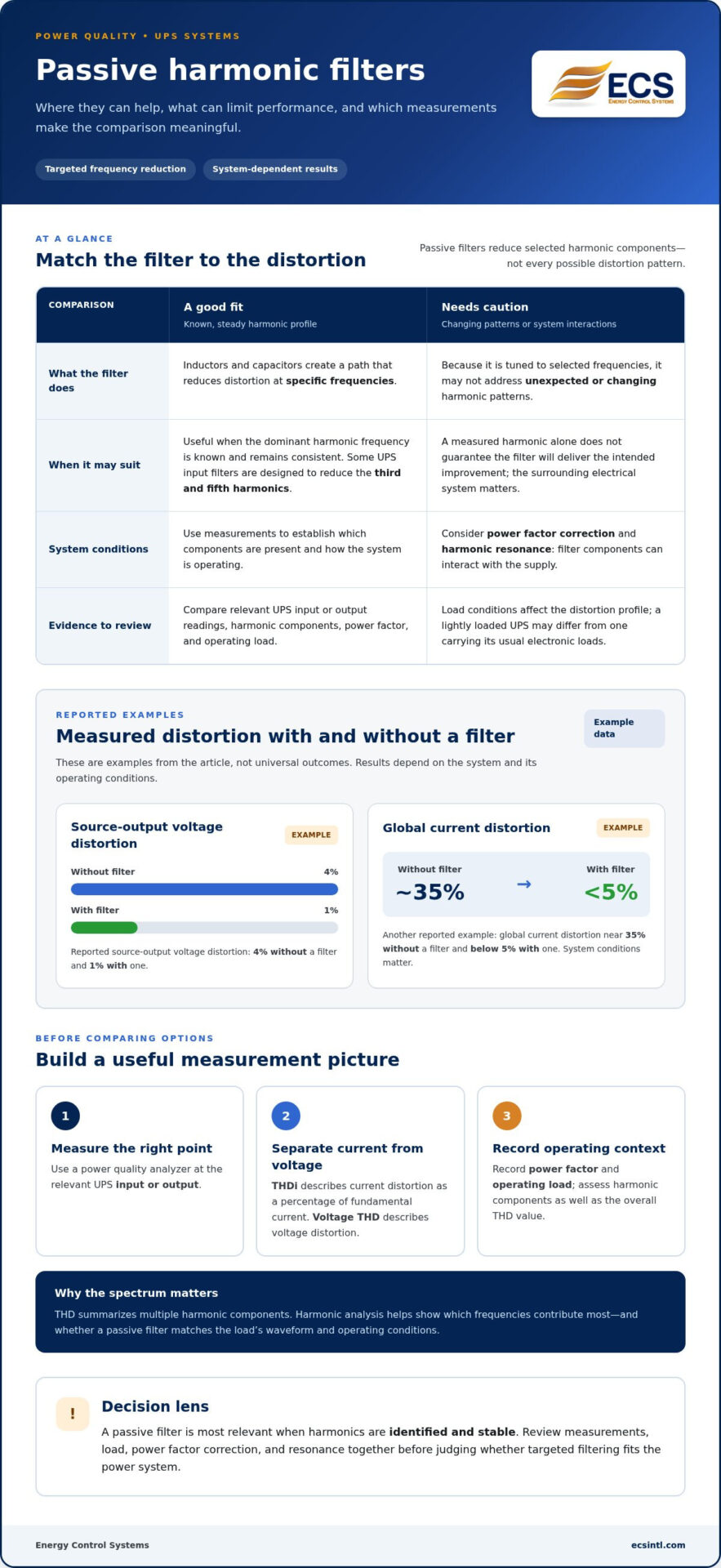
Use a power quality analyzer to measure distortion, assessing current THDi and voltage THD at the relevant UPS input or output. Record power factor and operating load as well. A lightly loaded UPS may show a different current-distortion profile from one carrying its usual electronic loads.
Passive harmonic filters
Passive filters reduce selected harmonic components in UPS power systems. Their effectiveness depends on how well the filter matches the distortion present.
How Passive Filters Reduce Harmonics
Inductors and capacitors form a path that reduces distortion at specific frequencies. This makes passive filtering useful when the dominant harmonic frequency is known and remains consistent. Some UPS systems include input filters designed to reduce the third and fifth harmonics. In one example, source-output voltage distortion measured 4% without a filter and 1% with one. These values illustrate an example, not a universal result.
Limitations of Passive Filters
A passive filter is tuned to specific frequencies, so it may not address changing or unexpected harmonic patterns. Its performance also depends on the surrounding electrical system. Account for power factor correction and harmonic resonance, since filter components can interact with the supply. Without understanding these conditions, a filter may not deliver the intended improvement, even if it targets a measured harmonic.
Compare system measurements before choosing a filtering approach. One example reports global current distortion near 35% without a filter and below 5% with one, but system conditions matter. A power quality analyzer can identify the distortion profile, while harmonic analysis helps interpret which frequencies need attention. This evidence supports a better-matched filter decision and helps assess whether passive filtering suits the load’s waveform and operating conditions.
For UPS installations with known, stable harmonics, harmonic analysis can help inform filter selection and evaluate power-quality needs.
Definition and causes of total harmonic distortion
Electrical waveforms combine a fundamental frequency with additional harmonic components. Total harmonic distortion describes how those components alter the waveform.
Meaning of Total Harmonic Distortion
Total harmonic distortion (THD) compares harmonic content with the fundamental component of an electrical waveform. Current THD, or THDi, expresses current distortion as a percentage of fundamental current; voltage THD describes voltage distortion. Keeping these measures distinct helps identify whether the central concern is current drawn by equipment or voltage quality.
Harmonic frequencies occur at multiples of the grid’s 50 or 60 Hz fundamental. For example, the second harmonic of a 50 Hz supply is 100 Hz. THD summarizes multiple components, rather than identifying one frequency by itself. A reading therefore describes overall distortion, while a harmonic spectrum helps show which components contribute most.
Causes of Total Harmonic Distortion
Nonlinear electrical loads draw current in pulses, producing harmonics that contribute to distortion. Variable frequency drives and LED lights are examples of power electronics that can generate harmonics. Six-pulse converter frequency inverters produce notable fifth- and seventh-order harmonic currents, which may combine with distortion from other equipment.
UPS rectifiers and inverters can also contribute through nonlinear conduction and rapid switching. The resulting harmonic current interacts with system impedance, turning current distortion into voltage distortion. This matters because the same current harmonics can affect voltage differently in systems with different impedance.
For a useful assessment, distinguish current THDi from voltage THD, then examine the harmonic components and operating load. That gives a clearer picture than treating one overall THD value as the whole diagnosis. Request harmonic analysis to understand the distortion profile in your power system.
Energy Control Systems: Uninterruptible Power Supplies (UPS)
Energy Control Systems offers Harmonic Analysis to help you understand distortion across your power system. It can be a useful next step if UPS or load measurements show elevated THD, equipment behaves unexpectedly, or you need to assess whether a passive filter suits the harmonic profile. Reviewing measured components alongside system conditions helps clarify the power-quality issue before you choose an approach.
Energy Control Systems also offers Uninterruptible Power Supplies (UPS) for organizations planning backup power around their electrical needs. Consider harmonic performance alongside continuity, especially when sensitive equipment and nonlinear loads share a system. A clear understanding of your requirements supports a more informed UPS decision.
Contact Energy Control Systems to discuss Harmonic Analysis or UPS requirements for your power system.
Make Your Next Power Decision with Confidence
Turn power-quality concerns into a clear planning priority. If harmonic distortion in UPS systems is affecting equipment decisions, let measured system needs guide your next step rather than choosing a filter by assumption.
Energy Control Systems offers professional Harmonic Analysis along with advanced transient voltage surge suppression and filtering solutions. These offerings can support an informed discussion about your power-quality requirements and potential solutions.
Discuss your power-quality needs with Energy Control Systems, and move forward with greater clarity.
Frequently Asked Questions
What Are Harmonics?
Harmonics are electrical waveform components at whole-number multiples of the supply’s fundamental frequency. For example, a 50 Hz supply has a second harmonic at 100 Hz. These components can be present in current, voltage, or both. Looking at individual harmonic orders, rather than only an overall distortion reading, helps identify which components are most prominent.
What causes harmonic distortion in UPS systems?
UPS rectifier switching, inverter operation, and connected nonlinear loads can all contribute to distortion. For example, a computer power supply may draw current in pulses, while a UPS rectifier also draws nonsinusoidal input current. The resulting distortion depends on how these sources interact with the electrical system. Comparing readings at the UPS input and output can help show where distortion is most pronounced.
What are typical THDi and THDv limits for UPS systems?
Useful design targets are input THDi below 5% and system voltage THDv below 5%. These are targets, not universal pass-or-fail limits for every installation. UPS rectifier design affects current distortion: active front-end rectifiers can have THDi below 3%, while 18-pulse rectifiers are typically around 5-8%. Compare specifications with measurements under representative operating conditions.
How do nonlinear loads affect UPS input and output harmonics?
Nonlinear loads, such as variable-speed drives and switched-mode power supplies, draw current that departs from a smooth sinusoidal waveform. Their harmonic currents can affect the supply feeding the UPS. At the output, the inverter must serve the connected load, so voltage quality depends on UPS design and load conditions. Assess input current and output voltage separately.
What IEEE 519 limits apply to UPS harmonic distortion in the United States?
IEEE 519 provides guidance on acceptable harmonic distortion, but it does not translate into one universal UPS-specific limit for every installation. The relevant assessment depends on the electrical system and where distortion is evaluated. Treat the below-5% THDv target as a useful design reference, not as a substitute for assessing the applicable system conditions and measured waveform.

Article by
Jeff Edwards
Founder of ECS International Inc. Edwards travels and speaks extensively in Latin America, Asia and Africa on the subject of power quality; transients and mitigating their impact on profitability. After graduating from Texas Tech University in Lubbock Texas, Edwards spent 9 years in the Telecommunications sector prior to founding Energy Control Systems in 1987 as a Texas based corporation selling surge suppression and UPS systems. The company has evolved into a global power quality products and energy efficiency concern with operations spanning South America, Asia, Europe and Africa.
Disclaimer
Some of the above information may be the opinion of the author.