

Electrical noise in a servo system often starts with power-supply problems or electromagnetic interference from drives, motors, and nearby high-power equipment. Protecting robotic arms from electrical noise means controlling how interference enters and travels through the system: use clean, stable power, separate high-power and signal cables, and maintain effective shielding and grounding.
A disrupted encoder signal or unreliable communication can make a fault frustrating to trace. Practical design choices can reduce the risk.
This article covers common noise sources and how cable routing, shielding, grounding, and power conditioning can help limit interference. It also explains how industrial EMC immunity and emissions standards relate to robotic systems, helping you understand what protection involves and where to focus.
Key Takeaways
- Preserve shielding across cable connections and enclosures; gaps or weak terminations can undermine the barrier.
- Understand how industrial immunity and emissions standards address different sides of electromagnetic compatibility.
- Trace servo noise to its source by distinguishing power-supply issues from interference and inspecting connections and components.
- When power quality is a concern, Uninterruptible Power Supplies (UPS) and Harmonic Analysis can help address the electrical conditions affecting servo systems.
How to reduce the noise of a servo robot?
Limit interference by controlling its path through the supply, cables, connections, and robot structure. Continuous shielding, careful cable routing, and suitable components help protect sensitive feedback and control signals.
Continuous Cable and Enclosure Shielding
Continuous shielding creates a conductive barrier across cables, connectors, and enclosures, limiting electromagnetic interference. A 360-degree shield connection maintains coverage around the cable instead of relying on a small contact point. Specify shield coverage and connector termination in cable assembly RFQs. Include enclosure interfaces and bending demands, since gaps or flexing can weaken shielding during robot motion.
Separating Power and Signal Cable Routes
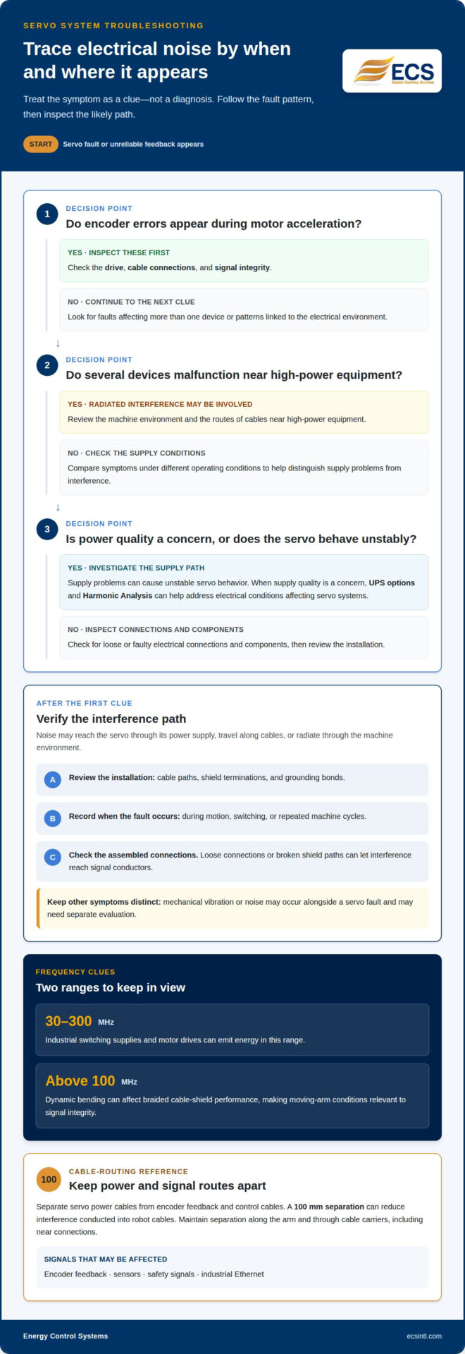
Separate servo power cables from encoder feedback and control cables to reduce interference coupling. Keep high-power routes away from sensitive signal cables where possible; a 100 mm separation can reduce interference conducted into robot cables. Maintain that separation along the arm and through cable carriers, rather than allowing power and signal cables to converge at connections. Interference can disrupt encoder feedback, sensors, safety signals, and industrial Ethernet, affecting motion accuracy and safe operation.
Grounding and Bonding the Robot Arm
Grounding provides an electrical path to ground, while bonding connects conductive parts so they work together to control noise. Bond cable shields to connector shells and conductive enclosures with broad, continuous contact rather than a long, narrow connection. Keep shield terminations intact through moving joints and check the assembled connections. Poor bonding can break the shielding path, allowing interference to reach signal conductors even when the cables are shielded.
EMI Protection Components and Costs
Ferrite cores, filters, and surge protectors address different disturbances, so choose them based on the noise path and affected circuit. For the recommended ferrite, pass the cable through the core twice. Select a filter suited to interference on the supply; a surge protector addresses voltage surges, not every form of EMI. Component choice, cable length, and installation scope affect costs, with pricing provided after a quote request.
Industrial EMC immunity and emissions standards
Electromagnetic compatibility (EMC) addresses both immunity and emissions. Immunity describes how equipment continues operating amid electromagnetic disturbance. Emissions are the interference a device releases into its surroundings. For a robot cable assembly, EMC performance depends on how components work together during movement, not on a connector specification alone.
IEC 61000-6-2 covers generic immunity requirements for equipment in industrial locations when no dedicated product or product-family standard applies. Its radiated-field test range is 80 MHz to 1 GHz at 10 V/m. This provides a reference for evaluating whether industrial equipment can withstand electromagnetic fields. Safety-critical robot applications may require 30 V/m immunity, depending on the application.
Emissions standards address the other direction. IEC 61000-6-4 covers generic emissions requirements for industrial environments within its scope. In North America, FCC Part 15 establishes emissions limits for robot systems, with Class A and Class B requirements depending on the intended operating environment. EN 55011 addresses industrial, scientific, and medical equipment, including industrial robots.
ISO 10218 incorporates EMI compliance requirements intended to help prevent interference from compromising safety-related control functions or emergency-stop systems. Standards do not replace sound design: unshielded data channels can interfere with other robots, machines, or computers. Evaluate the complete robot cable assembly, including shielding, connections, and the equipment it serves. Match immunity and emissions testing to the robot’s industrial environment, control devices, and motion profile. This supports more reliable signal transfer and reduces the risk of interference disrupting operation.
Causes of electrical noise in servo systems
Electrical noise usually reaches a servo system through its power supply or as electromagnetic interference (EMI). Servo motors, motor drives, variable-frequency drives, inverters, switching power supplies, and relays can create interference. It may travel along cables or radiate through the machine environment, reaching feedback and control circuits.
Changing fault patterns can help identify the source. If encoder errors appear during motor acceleration, inspect the drive, cable connections, and signal integrity. If several devices malfunction near high-power equipment, radiated interference may be involved. Supply problems can also cause unstable servo behavior, so compare symptoms under different operating conditions.
Start diagnosis by checking electrical connections and components for looseness or faults. Review the installation, including cable paths, shield terminations, and grounding bonds. Then note whether the fault occurs during motion, switching, or repeated machine cycles. These observations can help distinguish conducted interference from radiated EMI. Mechanical vibration or noise may occur alongside a servo fault and may warrant separate evaluation.
Frequency matters because shielding and cable assemblies behave differently across frequency ranges. Industrial switching supplies and motor drives can emit energy in the 30-300 MHz range. Dynamic bending can also affect braided cable-shield performance above 100 MHz, making moving-arm conditions relevant to signal integrity. A stable supply, sound connections, and an intact shield path each address a different entry point. Treat the symptom as a clue, not a diagnosis; protecting robotic arms from electrical noise begins by tracing the disturbance to its source.
If supply quality is a concern, review options for servo power concerns.
Energy Control Systems
Energy Control Systems helps address power-quality concerns affecting servo systems. If an unstable supply is suspected, an Uninterruptible Power Supply (UPS) may support continuity of power. Harmonic Analysis can help identify distortion in the electrical system and provide clearer insight into a potential source of interference.
These offerings address power conditions, not cable-routing or shielding faults. Consider them when symptoms point to supply disturbances or harmonics rather than a damaged connection or poorly terminated cable. Distinguishing between these causes helps focus the next step and reduce guesswork during troubleshooting.
For help addressing power-quality concerns affecting your servo system, contact Energy Control Systems.
Build Noise Control Into Your Next Upgrade
A durable plan for protecting robotic arms from electrical noise accounts for future changes, not just today’s fault. As equipment or production demands shift, document system modifications and recurring symptoms. This record can help your team spot patterns and make better-informed maintenance decisions.
Energy Control Systems offers advanced industrial transient voltage surge suppression solutions designed specifically for heavy-duty power protection. Matching a mitigation product to your robotic system starts with understanding the precise power-quality concern you need to address.
Take the next step at a pace that works for your team. Contact Energy Control Systems to discuss your power-quality needs and keep planning with confidence.
Frequently Asked Questions
What causes electrical noise and electromagnetic interference in robotic arms?
Common causes include power-supply disturbances and electromagnetic interference from switching or high-power equipment. A servo fault that coincides with drive or inverter activity may point to an electrical source. Loose connections or faulty components can also cause intermittent symptoms. Compare fault timing with machine events, then inspect electrical connections and components to narrow down the cause before changing control settings.
How can robotic arm cables be shielded and routed to reduce EMI?
Shield the cables and choose a construction suited to the arm’s full range of movement. Dynamic flexing can reduce braided-shield effectiveness by 20-40 dB above 100 MHz compared with static conditions. Standard polyester-backed aluminum foil shields typically fail after 500,000 flex cycles. Account for repeated bending and twisting, and evaluate shielding in the installed moving cable assembly.
How can servo drives and motors be isolated from sensitive robot sensors and controls?
Plan the layout to limit noise coupling from drives and motors into sensor and control circuits. Treat encoder feedback, machine vision, safety signals, and industrial Ethernet as sensitive paths. Interference can radiate through the environment as well as travel along wiring, so assess both routes in the assembled system. A cabinet partition alone may not address every path.
What wiring practices reduce noise in encoder, sensor, and communication cables?
Choose cable and connector combinations suited to the signal, EMI environment, grounding, and mechanical demands. Vibration, bending, twisting, and repeated mating can affect contacts and shielding over time. A connector specification alone does not establish system performance. Evaluate the complete cable-and-connector assembly under its intended conditions, including the movement that can trigger intermittent feedback or communication faults.
What EMC standards apply to industrial robots in the United States?
In the United States, FCC Part 15 sets emissions limits for robot systems, with Class A and Class B requirements depending on the intended operating environment. IEC 61000-6-2 covers generic industrial immunity when no relevant dedicated product or product-family standard exists; IEC 61000-6-4 covers generic industrial emissions. ISO 10218 includes EMI compliance requirements related to safety control functions and emergency-stop systems.

Article by
Jeff Edwards
Founder of ECS International Inc. Edwards travels and speaks extensively in Latin America, Asia and Africa on the subject of power quality; transients and mitigating their impact on profitability. After graduating from Texas Tech University in Lubbock Texas, Edwards spent 9 years in the Telecommunications sector prior to founding Energy Control Systems in 1987 as a Texas based corporation selling surge suppression and UPS systems. The company has evolved into a global power quality products and energy efficiency concern with operations spanning South America, Asia, Europe and Africa.
Disclaimer
Some of the above information may be the opinion of the author.