

An MCC can have surge protection at its incoming supply and still leave critical control or communication circuits exposed. Effective spd for motor control center (mcc) protection takes a coordinated view of the system, not a one-device approach. Transients can reach equipment through different paths, so begin by identifying the circuits and connections that matter to your operation.
To decide where protection belongs, start with the MCC’s electrical conditions and the equipment connected to it. Map incoming power, control power, and signal or network connections. Then compare candidate SPDs with the circuit ratings, grounding arrangement, panel design, and installation location. This guide outlines a practical assessment, what to record, and when broader power-quality analysis can help clarify the problem.
Key Takeaways
- Plan spd for motor control center (mcc) protection in coordinated layers, considering incoming power as well as vulnerable control and communication circuits.
- Use a repeatable assessment: document system conditions, map circuits, assess exposure, review SPD data, and verify applicable requirements.
- Evaluate voltage, grounding, short-circuit conditions, and installation location against the specific MCC and site.
- Record protection points and commissioning checks. Consider broader power-quality analysis when symptoms may involve harmonics as well as transients.
Why an MCC Needs Surge Protection Beyond the Main Power Connection
A surge protective device (SPD) is intended to limit transient overvoltage at a protected electrical circuit. In a motor control center, that circuit might be part of the incoming power supply, control power, or a downstream signal path. An SPD at the main connection addresses that point, but does not automatically protect every circuit and connected device.
An MCC brings motor control and related equipment together in one assembly. The Motor Control Center (MCC) overview explains its common role in organizing motor control units and associated components. Transients can affect power components, while sensitive electronics may also be exposed through control wiring or connections to other equipment. Depending on the installation, this may include PLCs, variable frequency drives, or automation systems communicating over a network. A disturbance along one of these paths can disrupt equipment or interrupt production, even when the incoming power connection has protection.
Which MCC circuits and connected equipment deserve attention?
Separate the MCC’s incoming power connection from its control power and downstream signal or network connections. Trace how critical equipment receives power and communicates. For each device, note the circuits it connects to and consider which paths could carry a transient to vulnerable electronics. A PLC, drive, or network connection is a point to assess, not an automatic reason to install a separate SPD. The right protection points depend on the MCC design, connected loads, exposure, and facility power system.
Protection planning follows the circuit: an SPD at one connection does not necessarily protect equipment reached through another. Map the paths first, then assess which protection points suit the installation. This is the practical starting point for evaluating an spd for motor control center (mcc) application.
How to Select an SPD for an MCC: A Practical Assessment Sequence
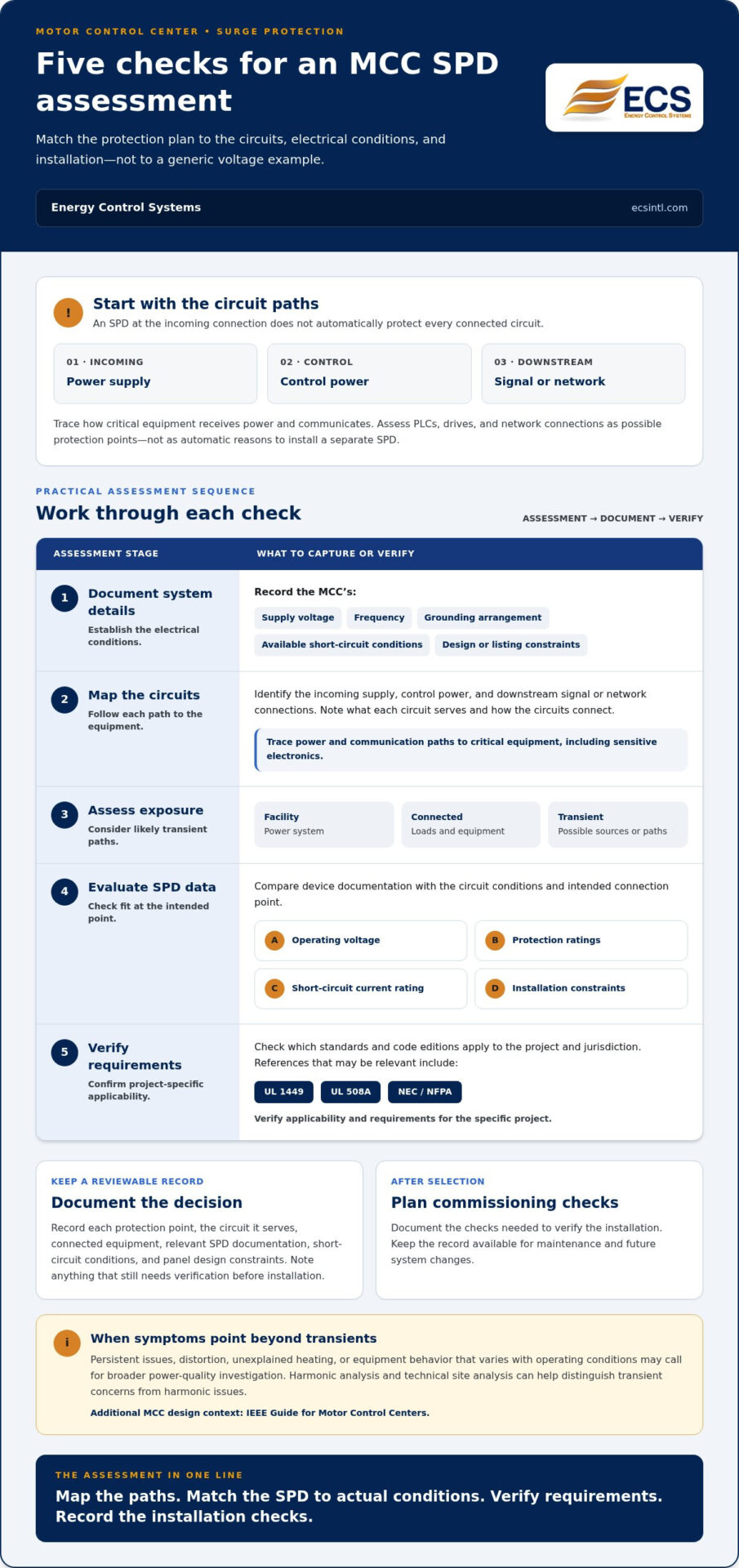
Choose an SPD based on the MCC’s actual electrical conditions, not a generic voltage example. Work through these steps to make the spd for motor control center (mcc) assessment specific to the installation:
- Document system details. Record supply voltage, frequency, grounding arrangement, available short-circuit conditions, and MCC design or listing constraints.
- Map the circuits. Identify the incoming supply, control power, and downstream signal or network connections. Note the equipment each circuit serves and how the circuits connect.
- Assess exposure. Consider the facility power system, connected loads, and likely sources or paths of transient overvoltage.
- Evaluate SPD data. Compare the device documentation, including operating voltage and protection ratings, with the circuit conditions and intended connection point. Check the short-circuit current rating and installation constraints as part of the fit.
- Verify requirements. Confirm which standards and code editions apply to the project and jurisdiction. UL 1449, UL 508A, and NEC/NFPA references may be relevant, but applicability and requirements need project-specific verification.
The IEEE Guide for Motor Control Centers can provide additional MCC design context. Use it as a reference, alongside confirmation of the requirements that govern the installation.
What should an MCC SPD assessment document?
Keep the record detailed enough for others to review the selection and plan the installation. Document the MCC supply characteristics, grounding arrangement, protected circuit and connection point, connected equipment, short-circuit conditions, SPD data, and applicable panel design constraints before selection. Compare device documentation with the required ratings and the panel’s listing or design limits. Record any items that still need verification so they are resolved before installation.
For broader site context, ECS provides power-quality analysis resources, including technical site analysis and harmonic analysis, to help assess facility conditions.
MCC Surge Protection Next Steps: From Assessment to a Coordinated Solution
Turn the assessment into a record your team can use. Document each selected protection point, the circuit it serves, the relevant SPD documentation, and the commissioning checks needed to verify the installation. Keep the record available for maintenance and future system changes. A coordinated plan should explain both what was selected and why it fits the MCC and facility conditions.
Symptoms that appear to be transient events can have other power-quality causes. If issues persist or occur alongside distortion, unexplained heating, or equipment behavior that varies with operating conditions, a broader investigation can help distinguish transient concerns from harmonic issues. Harmonic analysis and technical site analysis can add useful context to the protection plan. For MCC design background, consult the IEEE 1683-2025 Guide for Motor Control Centers.
How ECS can support an MCC power-quality plan
Energy Control Systems (ECS) specializes in power quality management and provides technical site analysis and harmonic analysis. These services help assess facility conditions and operational priorities as part of power-quality planning. ECS also offers the SineTamer LA, RM, and ST-PCMF series, along with Uninterruptible Power Supplies (UPS). Compare product documentation with the MCC circuit, installation conditions, and project requirements before selecting protection. For additional background, explore this industrial surge protection guide.
A documented, site-informed spd for motor control center (mcc) plan gives your team a clearer basis for protection decisions and follow-up. Discuss your power-quality needs with ECS to explore surge protection and analysis for your facility.
Build a Clearer Path to MCC Protection
Effective spd for motor control center (mcc) planning looks beyond the incoming supply. Map the power, control, and signal circuits that matter to your operation, then evaluate protection points against the MCC’s design, site conditions, and applicable requirements. Document SPD data and commissioning checks so the plan remains useful as equipment or facility needs change.
When power-quality symptoms are unclear, broader site analysis can help distinguish transient concerns from harmonic issues. Energy Control Systems provides technical site analysis and professional harmonic analysis, as well as SineTamer surge protection products and UPS systems. Match the protection approach to the project’s requirements and the facility’s conditions.
For help planning a coordinated approach, discuss your industrial power-quality needs with ECS.
Frequently Asked Questions
What is an SPD for a motor control center?
An SPD for a motor control center is a device intended to limit transient overvoltage at a protected electrical circuit. In an MCC, that circuit could be the incoming power connection or a control or signal path. The right spd for motor control center (mcc) application depends on the system design and which connected equipment needs consideration.
Where should an SPD be installed in an MCC?
Install an SPD at a location suited to the circuit and equipment it is intended to protect. The MCC incoming power connection may be one consideration, while control power and downstream signal or network circuits can create different paths to sensitive equipment. Review the connection point, voltage, grounding arrangement, short-circuit conditions, panel design, and applicable requirements for the specific installation.
Does an MCC need more than one surge protective device?
Not necessarily. One SPD may not address every circuit path, so an assessment could identify additional protection points for control or signal circuits alongside the incoming supply. Consider the MCC layout, connected equipment, facility exposure, and how circuits are interconnected. The goal is a coordinated plan based on site needs, not multiple devices by default.
How do you choose the right SPD rating for an MCC?
Match the SPD’s documented ratings to the actual MCC circuit and installation conditions. Review operating voltage, grounding configuration, connection location, and short-circuit conditions, as well as device ratings such as MCOV, VPR, and SCCR. Compare the device documentation with panel design constraints, then verify which standards and code editions apply to the project and jurisdiction before selection.

Article by
Jeff Edwards
Founder of ECS International Inc. Edwards travels and speaks extensively in Latin America, Asia and Africa on the subject of power quality; transients and mitigating their impact on profitability. After graduating from Texas Tech University in Lubbock Texas, Edwards spent 9 years in the Telecommunications sector prior to founding Energy Control Systems in 1987 as a Texas based corporation selling surge suppression and UPS systems. The company has evolved into a global power quality products and energy efficiency concern with operations spanning South America, Asia, Europe and Africa.
Disclaimer
Some of the above information may be the opinion of the author.