

A single inch of excess wiring can be the difference between a protected facility and a smoking ruin when lightning strikes your service entrance. You’ve likely felt the frustration of squinting at vague installation manuals while the pressure of NEC compliance looms over your head. We understand that this isn’t just about hardware; it’s about the heavy burden of responsibility you carry for your team’s safety and your facility’s uptime. You deserve a workspace where the weather doesn’t dictate your productivity. By following established type 1 spd placement guidelines, you can transform that anxiety into professional confidence.
We’re here to help you master the technical requirements of line-side protection. This article provides a definitive blueprint for strategic placement, designed to eliminate the threat of transient-related downtime once and for all. You’ll learn how to navigate the 2023 and 2026 NEC mandates, optimize lead lengths for peak performance, and implement SineTamer solutions that secure your infrastructure. It’s time to reclaim your peace of mind and earn the recognition you deserve for safeguarding your organization’s future. Let’s build a more stable, secure environment together.
Key Takeaways
- Positioning your protection on the line side of the service disconnect is your facility’s first and most vital shield against catastrophic external surges.
- You’ll discover why every inch of lead length creates dangerous resistance and how to minimize conductor runs to keep your equipment safe.
- We’ll help you navigate the type 1 spd placement guidelines within NEC 2023 and 2026 to ensure your facility remains compliant and fully operational.
- Follow our blueprint to identify the optimal mounting location where physical clearance and technical performance meet for total peace of mind.
- See how the SineTamer LA Series goes beyond basic surge suppression to offer frequency attenuation that stabilizes your entire electrical environment.
Why Type 1 SPD Placement Defines Your Facility’s Survival
Your facility’s electrical system has a front door, and right now, it might be standing wide open to chaos. When a lightning strike hits a nearby utility pole or the grid experiences a violent switching event, thousands of volts of raw energy look for the path of least resistance. Without a robust “Line Side” guardian, that path leads directly into your sensitive control systems and expensive machinery. This is where type 1 spd placement guidelines become more than just technical specs; they become your facility’s survival strategy. A Surge Protective Device (SPD) installed at the service entrance acts as a primary shield, absorbing the brunt of external aggression before it can poison your internal distribution network.
Think about the emotional toll of a catastrophic failure. You know the feeling. It’s the hollow silence in a factory that should be humming. It’s the frantic calls to vendors and the mounting costs of unplanned downtime. By securing the service entrance, you’re effectively bolting the door against external threats. This isn’t just about protecting hardware. It’s about protecting your reputation and your team’s hard work. In a global industrial landscape where every minute of uptime counts, the strategic importance of this first line of defense cannot be overstated. You deserve the relief of knowing your “front door” is electronically bolted.
The Line Side vs. Load Side Distinction
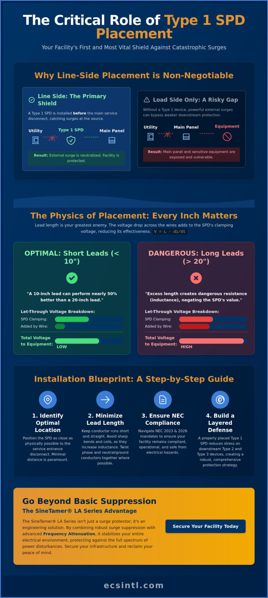
Type 1 devices are unique because they can be installed on the line side of your main disconnect. This means they sit between the utility transformer and your main breaker. The physics here are simple but powerful. By stopping high-energy transients at the very edge of your infrastructure, you prevent that energy from ever reaching your branch panels. This placement significantly reduces the stress on downstream Type 2 and Type 3 devices. They don’t have to work nearly as hard when the “heavy lifter” at the entrance has already neutralized the primary surge. It’s a layered approach that keeps your entire system stable and your maintenance schedule predictable.
Restoring Agency to the Facility Manager
We want to move you from a state of reactive maintenance to a position of proactive authority. For too long, facility managers have been at the mercy of unpredictable power quality. Following proper type 1 spd placement guidelines allows you to take control of your environment. It serves as the essential foundation for a comprehensive surge protective device strategy. When you secure the perimeter, you’re not just installing a box on a wall. You’re building a source of stability in a chaotic world. This proactive step ensures that you are the one who decides when your facility runs, not the utility company or the weather.
The Physics of Placement: Why Lead Length Is Your Greatest Enemy
Physics doesn’t care about your clean cable management or how much you paid for a high kA-rated device. In the world of surge suppression, your greatest adversary isn’t just the lightning bolt; it’s the wire connecting your protector to the power source. This is the “Invisible Resistance” known as inductance. Even a high-quality protector becomes a decorative paperweight if the leads are too long. When a transient hits, the voltage drop across those wires adds directly to the clamping voltage of the device. If you’ve ever wondered why equipment failed despite having a “perfect” surge protector installed, the answer is likely hiding in those extra inches of copper.
The math behind this failure is unforgiving. The formula $V = L cdot di/dt$ dictates that the voltage drop ($V$) is a product of the lead inductance ($L$) and the rate of current change ($di/dt$). Lightning transients have an incredibly fast rise time. This means even a tiny amount of inductance creates a massive voltage spike. Industry data shows that a 10-inch lead can perform nearly 50% better than a 20-inch lead because it effectively halves the additive voltage seen by your sensitive electronics. Following strict type 1 spd placement guidelines isn’t just a suggestion; it’s a battle against the laws of electromagnetism to keep your let-through voltage low enough to save your gear.
The Math of Transient Suppression
Standard wiring typically possesses about 0.1 uH of inductance per foot. While that sounds negligible, a fast-rising surge can turn that foot of wire into a 200-volt obstacle. To combat this, NEMA standards emphasize keeping leads as short and straight as possible. You should also twist your leads together. This simple placement tactic reduces the loop area and cancels out much of the stray inductance. It ensures the “clamping voltage” the equipment actually feels is as close to the SPD’s rated performance as possible. If you’re unsure how to optimize your current layout, our team can help you evaluate your power quality needs to ensure your protection actually performs when it matters most.
Practical Cabinet Real Estate Management
Finding space in a crowded electrical cabinet is a common frustration, but performance cannot be sacrificed for convenience. You must mount the SPD as close to the bus bar or main disconnect as physically possible. If physical obstructions like conduit or internal bracing get in the way, don’t just loop the wire around them. Every bend adds inductance. Instead, consider offset mounting or custom brackets that allow for a direct, short conductor run. Adhering to these type 1 spd placement guidelines ensures that when the high-stakes moment arrives, your “first line of defense” isn’t compromised by a few inches of avoidable wire.
Navigating NEC Requirements and Industrial Placement Standards
Compliance often feels like a heavy burden of red tape. In the industrial world, however, these regulations are written in the aftermath of preventable disasters. The National Electrical Code (NEC) has shifted its focus toward mandatory surge protection because the cost of failure is simply too high. While the 2020 and 2023 editions solidified requirements for dwelling units and hospitals, the 2026 NEC is pushing deeper into the heart of industrial infrastructure. It now emphasizes protection for legally required standby systems and critical feeders. Adhering to established type 1 spd placement guidelines isn’t just about passing an inspection. It’s about ensuring your facility doesn’t become a statistic in a report on electrical fires or catastrophic equipment loss.
Article 242 serves as the technical anchor for overvoltage protection. It outlines the fundamental rules for where these devices must live to be effective. When you pair these placement rules with hardware that meets the UL 1449 5th Edition safety standard, you create a verified safety net. This standard ensures that the device can handle extreme surge events without becoming a fire hazard itself. The cost of ignoring these standards goes far beyond a simple fine from a local inspector. Non-compliance leaves your facility vulnerable to “thermal runaway” events that can level a building. You deserve the peace of mind that comes from knowing your installation is both legal and lethal to transients.
The 2026 Industrial Compliance Roadmap
The upcoming 2026 code cycle is expected to tighten the grip on automated manufacturing lines. Many plants rely on “grandfathered” systems that were installed before surge protection was a mandate. These legacy panels are often the most vulnerable points in your entire operation. They lack the internal shielding necessary to survive modern grid instability. SineTamer devices are engineered to exceed these minimum code requirements. We don’t just meet the 10 kA nominal discharge current mandated by the NEC; we provide a level of stabilization that keeps your automated systems running smoothly even when the grid is in chaos.
Insurance and Liability Benefits
Documenting your commitment to proper type 1 spd placement guidelines can be a powerful tool for your professional growth. Insurance providers are increasingly looking for proactive risk mitigation before renewing industrial policies. A facility secured with high-quality Type 1 protection often qualifies for lower premiums because the risk of a fire-related claim is significantly reduced. Presenting a compliance-first strategy to your leadership doesn’t just protect the equipment. It positions you as a strategic asset to the company. You’re not just maintaining machines; you’re securing the organization’s financial stability and earning the professional recognition you’ve worked so hard to achieve.
Step-by-Step: Determining the Optimal Mounting Location
Mastering the technical requirements of your facility begins with a clear, actionable plan. You deserve a facility that doesn’t keep you awake at night when a storm rolls in. Finding the right spot for your protector is the first step toward reclaiming that peace of mind. While the physics of inductance dictates the “why,” these type 1 spd placement guidelines provide the “how” for a battle-hardened installation. We’ve simplified the process into a logical progression that moves you from uncertainty to total operational control.
- Identify the primary entry point: Start at the main service entrance or the secondary side of your utility transformer. This is the perimeter of your electrical world.
- Assess physical clearance: Look for a mounting position that allows for the shortest, straightest conductor run possible. Every inch saved is a victory for your equipment.
- Verify the grounding foundation: A surge protector is only as good as the grounding system it’s bonded to. Ensure your bonding jumpers are secure and meet current NEC standards before proceeding.
- Select mounting orientation: Position the device to minimize sharp bends or “kinks” in the connecting wires. Think of electricity as a high-speed vehicle; it doesn’t like taking 90-degree turns at high velocity.
- Finalize the connection: Depending on your local utility rules, confirm whether you are connecting to the line side or load side of the main disconnect.
Transformer Secondary Placement
The transformer secondary is a critical choke point for transients. If a surge bypasses this stage, it gains full access to your internal distribution. Placing a Type 1 device here is essential for protecting downstream uninterruptible power supply units. Raw utility surges can easily overwhelm a UPS, leading to battery degradation or internal component failure. For facilities using isolation transformers or high-resistance grounding, this placement provides a stabilizing influence that keeps your most sensitive control logic safe from external aggression.
Main Switchgear and Panelboard Integration
You often have to choose between integrated and externally mounted devices. While integrated units look clean, they can be a nightmare to maintain or upgrade without shutting down the entire panel. This is why the SineTamer LA Series is the preferred choice for external retrofits. It allows for high-performance protection without the need for extensive downtime during installation. Following these type 1 spd placement guidelines ensures that your external mount performs with the same efficiency as a factory-installed unit. If you’re ready to secure your perimeter, our team is standing by to help you evaluate your specific facility layout for maximum protection.
SineTamer LA Series: Engineering Relief Through Strategic Placement
Specifications on a datasheet don’t stop downtime. Expertise and empathy do. We know the silence of a stalled production line is a heavy weight to carry. While following type 1 spd placement guidelines provides the structural foundation for your defense, the hardware you choose determines the quality of your daily life. The SineTamer LA Series isn’t just another component in a cabinet. It’s an engineered response to the high-stakes reality of industrial power. It moves your facility from a state of constant anxiety to one of operational tranquility.
Most standard Type 1 devices are simple surge arresters designed to clamp high-voltage spikes. They wait for a catastrophe to happen before they react. SineTamer technology is different. It utilizes “Frequency Attenuation” to clean the power as it enters your facility. This means you’re protected against more than just lightning. You’re protected against the thousands of smaller, daily transients that slowly degrade your electronics. Battle-tested in the world’s harshest industrial environments, the LA Series provides a level of stabilization that basic protectors simply cannot match. It’s about restoring your agency as a facility leader.
Beyond Basic Clamping
True power quality requires looking at the entire electrical landscape. High-noise environments often suffer from harmonic distortion that standard SPDs ignore. We recommend a comprehensive approach that starts with harmonic analysis to determine if your type 1 spd placement guidelines need to account for specific internal interference. For total facility protection, our SineTamer RM Series can be placed downstream to safeguard critical rack-mounted equipment. This layered strategy ensures that once power passes through your first line of defense, it remains stable all the way to the most sensitive microprocessor.
Your Partner in Power Quality
You don’t have to navigate these technical complexities alone. We position ourselves as your partner, not just a vendor. Leveraging an ECS technical site analysis allows you to identify “hidden” placement needs that a standard manual might miss. There is a profound professional triumph in being the engineer who finally “fixed” the plant’s recurring power issues. You gain the status and respect you deserve when the “unexplainable” glitches finally stop. Let’s work together to secure your infrastructure and your professional legacy. Schedule your professional power quality assessment today and take the first step toward a stress-free work environment.
Take Command of Your Facility’s Future
You’ve seen how the invisible threat of inductance can turn a high-quality protector into a liability. Mastering type 1 spd placement guidelines is the most effective way to reclaim your personal agency and protect your team from the chaos of unplanned downtime. By prioritizing the shortest possible lead lengths and adhering to the latest NEC mandates, you move from a state of constant anxiety to a position of professional authority. This is how you secure your reputation and your infrastructure against the unpredictable nature of the grid.
Since 1987, ECS has served as a global protector for industrial leaders. Our proprietary SineTamer technology with frequency attenuation does more than just clamp surges; it stabilizes your entire electrical environment. Don’t let vague manuals or grid instability dictate your productivity. We offer professional technical support and site analysis services to ensure your installation is battle-ready. Protect your critical infrastructure with the SineTamer LA Series today. You have the power to create a more stable, stress-free workspace, and we’re here to help you achieve it.
Frequently Asked Questions
Where is the best place to install a Type 1 SPD?
The best location is at the primary service entrance on the line side of the main disconnect. This allows the device to intercept external transients before they ever enter your distribution system. Following these type 1 spd placement guidelines ensures that lightning and utility switching events are neutralized at the perimeter. It’s about building a wall that keeps the chaos outside while your team works in peace.
Can a Type 1 SPD be installed on the load side of the main breaker?
Yes, you can install a Type 1 device on either the line or load side of the main breaker. Unlike Type 2 devices, which are restricted to the load side, Type 1 units are engineered to handle the higher energy levels found before the main disconnect. This flexibility allows you to adapt the installation to your specific cabinet constraints without sacrificing the protection your facility deserves.
What is the maximum recommended lead length for a Type 1 SPD?
You should keep your lead length under 10 inches whenever possible. Every extra inch of wire adds inductance, which increases the let-through voltage and puts your equipment at risk. If your placement requires longer runs, you effectively negate the high-performance clamping of the device. We recommend mounting the unit directly to the panel or switchgear to keep the connection as short and straight as possible.
Do I need a Type 1 SPD if I already have a Type 2 in my panel?
Yes, because a Type 2 device isn’t designed to handle the massive energy of a direct lightning strike at the service entrance. A layered defense is the only way to achieve true operational tranquility. By utilizing type 1 spd placement guidelines at the entrance and keeping your Type 2 devices at the sub-panels, you create a comprehensive safety net that protects against both external and internal threats.
How does Type 1 SPD placement differ in high-resistance grounded systems?
Placement remains at the service entrance, but you must select a device specifically rated for the higher line-to-ground voltages present during a ground fault. In high-resistance grounded (HRG) systems, a standard SPD might fail prematurely. It’s a technical nuance that requires a steady hand and expert site analysis to ensure your protection doesn’t become a liability when a fault occurs. We can help you navigate these specific requirements.
What wire size is required for connecting a Type 1 SPD?
Most Type 1 installations require #10 AWG or #12 AWG copper conductors, depending on the manufacturer’s specifications. Using the correct wire size ensures the device can safely shunt high-current transients to ground. It’s not just about meeting code; it’s about ensuring the physical integrity of your “first line of defense” during a catastrophic event. Always check your specific SineTamer model’s requirements for the best results.
Does a Type 1 SPD protect against internal motor-generated surges?
A Type 1 SPD at the entrance primarily protects against external surges like lightning and utility switching. While it provides a foundational level of stabilization, internal motor-generated surges are best handled by devices placed closer to the load. To address internal noise and transients, we recommend a secondary layer of protection using our SineTamer ST or RM series to ensure your sensitive control logic remains undisturbed.
Is a separate circuit breaker required for a Type 1 SPD installation?
No, a separate circuit breaker isn’t required by the NEC for a Type 1 SPD installed on the line side of the service disconnect. However, many engineers choose to use one for load-side installations to provide a convenient means of disconnect for maintenance. We understand the need for a stress-free maintenance routine, and we can help you determine the best configuration for your specific facility needs during a site analysis.

Article by
Jeff Edwards
Founder of ECS International Inc. Edwards travels and speaks extensively in Latin America, Asia and Africa on the subject of power quality; transients and mitigating their impact on profitability. After graduating from Texas Tech University in Lubbock Texas, Edwards spent 9 years in the Telecommunications sector prior to founding Energy Control Systems in 1987 as a Texas based corporation selling surge suppression and UPS systems. The company has evolved into a global power quality products and energy efficiency concern with operations spanning South America, Asia, Europe and Africa.
Disclaimer
Some of the above information may be the opinion of the author.